Sample Drawing
- Home
- /
- Sample Drawing
Key Features in Our Detailed Embed/Anchor bolt are as:
- Enlarged anchor bolt pattern details shown on plan with highlighted A.B location which reduce the risk of misplacement of anchor bolt on plan. Similarly, we did for the Embed placement.
- Proper bearing level provided on the A.B/Embed with location which easily facility the A.B/Embed placement.
- We ensure the field verification of A.B placement with our drawings.
Key Features of Our Anchor Bolt and Embed Detailing:
- Comprehensive Plan Layouts: Enlarged anchor bolt patterns with clearly highlighted locations are included on the plan, significantly reducing the risk of misplacement during installation. Embed placements are detailed with the same precision.
- Accurate Elevation and Positioning: Bearing elevations and exact locations for all anchor bolts and embeds are provided, ensuring accurate and efficient on-site placement.
- Field Coordination Support: Our detailed drawings are designed to facilitate and support field verification, helping ensure anchor bolts are installed correctly the first time.

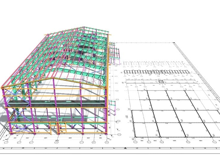
Key Features of Our Structural Steel Erection Drawings:
- Standardized Sheet Sizes and Scales: Drawings are presented on standard A1 (24" x 36") sheets using appropriate scales (1:36, 1:48, 1:64, 1:96), ensuring legibility and clarity for fabricators and erectors.
- Plan Orientation and Key Plans: Each plan includes a clear Plan North and Key Plan to guide navigation across sub-plans and details.
- Accurate Framing and Grid Dimensions: Framing plans are aligned with fixed grids and precise dimensions to support accurate layout and coordination.
- Defined Erection Pathways: Logical erection paths are shown on the plans, providing clear direction for the erector to efficiently begin and sequence installation.
- Connection Details and Orientation: Shear tab orientations and other key connections are clearly shown on plan, with sections and detail callouts placed as required by the project.
- Field Connection Clarity:Detailed field-welded and bolted connection information is provided, including erector keynotes for structural components such as SC, PT, moment, axial, and seismic connections, when applicable.
- Special Finishing Notes: Architectural exposed structural steel (AESS) and galvanization requirements are noted when needed.
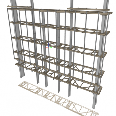
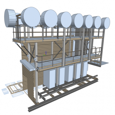
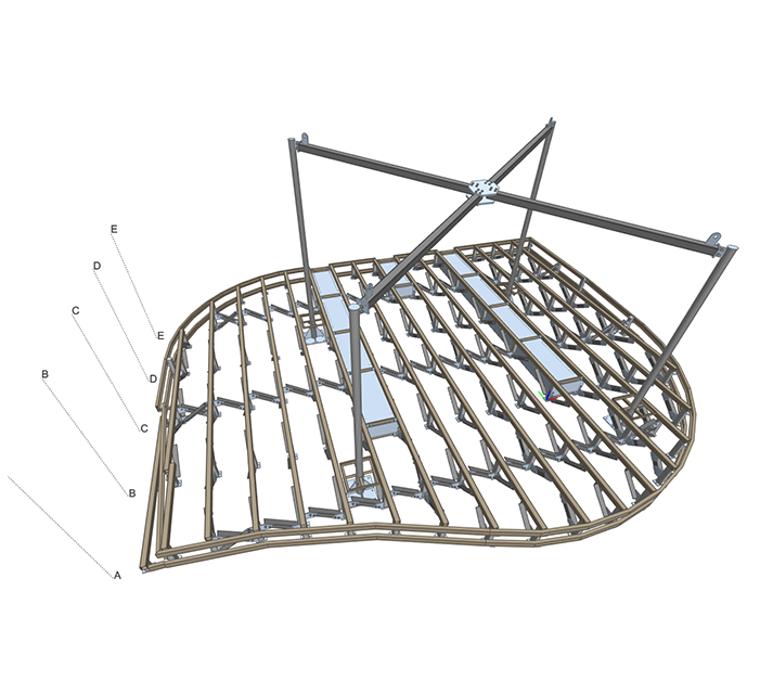
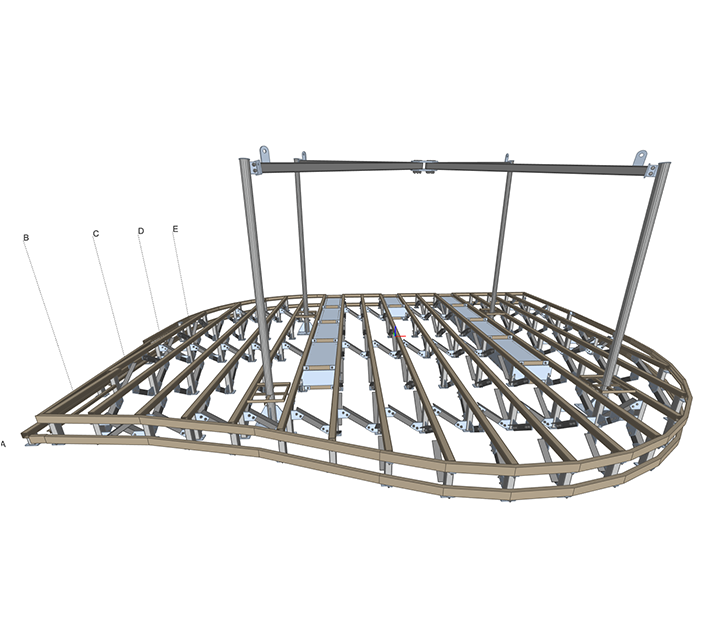
- 3D Isometric Views: Supplementary 3D isometric sheets are included to convey the overall structure and concept, enhancing visual understanding and project coordination.
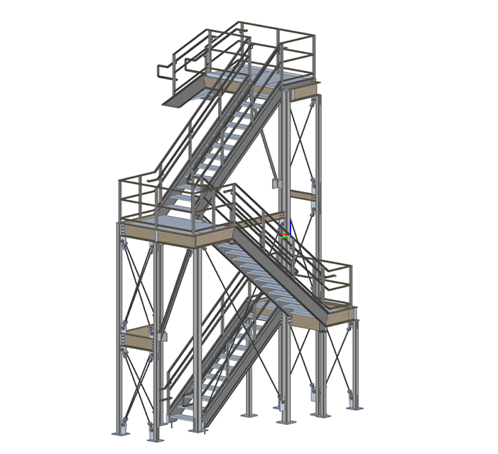
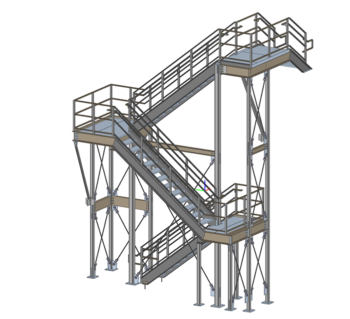
Key Features of Our Stair Detailing:
- Enlarged Stair Plans: Stair layouts are detailed using enlarged scale factors, ensuring clarity and precision for fabrication and installation.
- Comprehensive Section Views: Each stair plan includes sectional views showing all landing elevations, providing a complete understanding of vertical alignment and transitions.
- Special Finish Notes: AESS (Architecturally Exposed Structural Steel) and galvanization requirements are clearly noted when applicable.
- 3D Isometric Views: Dedicated 3D isometric sheets offer a visual overview of the stair design, enhancing conceptual clarity and on-site execution.

Key Features in Our Detailed Erections are as:
- We always use proper sheet size, A1(24 x36) and scale: 36, 48, 64 & 96 dimension scales which made our drawing legible and attractive for user.
- Plan North with Key Plan shown for sublet plan/detail.
- Plan framing fixed with proper grid dimensions.
- Proper pathway shown on the plan for the Erector to start work.
- Connection shear tab orientation shown on plan
- Proper section & detail refer on the framing plan per project requirement.
- Proper Field welded/bolted connection details with erector key notes on these details for SC, PT, Moment, Axial, seismic connection if any required.
- AESS & Galvanization notes if any required.
- 3D isometric view sheet added which gives the overall idea of the building and it concept.
Key Features in Our Detailed Stair are as:
- Stair plans detailed in enlarge scale (i.e, 24, 36 scale factor).
- Stair plans with each landing levels shown throughout section for proper understanding of stair.
- AESS & Galvanization notes if any required.
- 3D isometric view sheet added which gives the overall idea of the stair and it concept.